The goal of the shift was to perform some noise injections on the CO2 lasers by using their piezo (no need for access to the CO2 benches).
Using the calibrations performed during the maintenance [entry 63258], Matteo calculated the amplitude needed to observe in hrec the sinusoidal signal injected at 29 Hz, 68 and 85 Hz following the model reported in VIR-0911A-19. Note that the model is based on the superposition integral between the YAG and the DAS design profile but using the current applied powers.
WI
For the WI, the voltage needs to be set on the piezo to measure 10^20 1/sqrt (Hz)) at 29 Hz is 0.006 V. A first injection has been done (at 17.25.20 GPS 1392053138, 300s )) but nothing appeared on hrec. Thus, a subsequent attempt has been done by increasing the voltage up to 0.02 V (the maximum allowed voltage to not saturate the ISSIN signal) but the line didn't appear in the sensitivity curve.
In the table below, the main parameters of the injection are reported.
| WI | Freq [Hz] | Amplitude [V] | TCS WI CO2 ISSIN [V/sqrt(Hz)] | Time |
| | 29 | 0.02 | 0.028 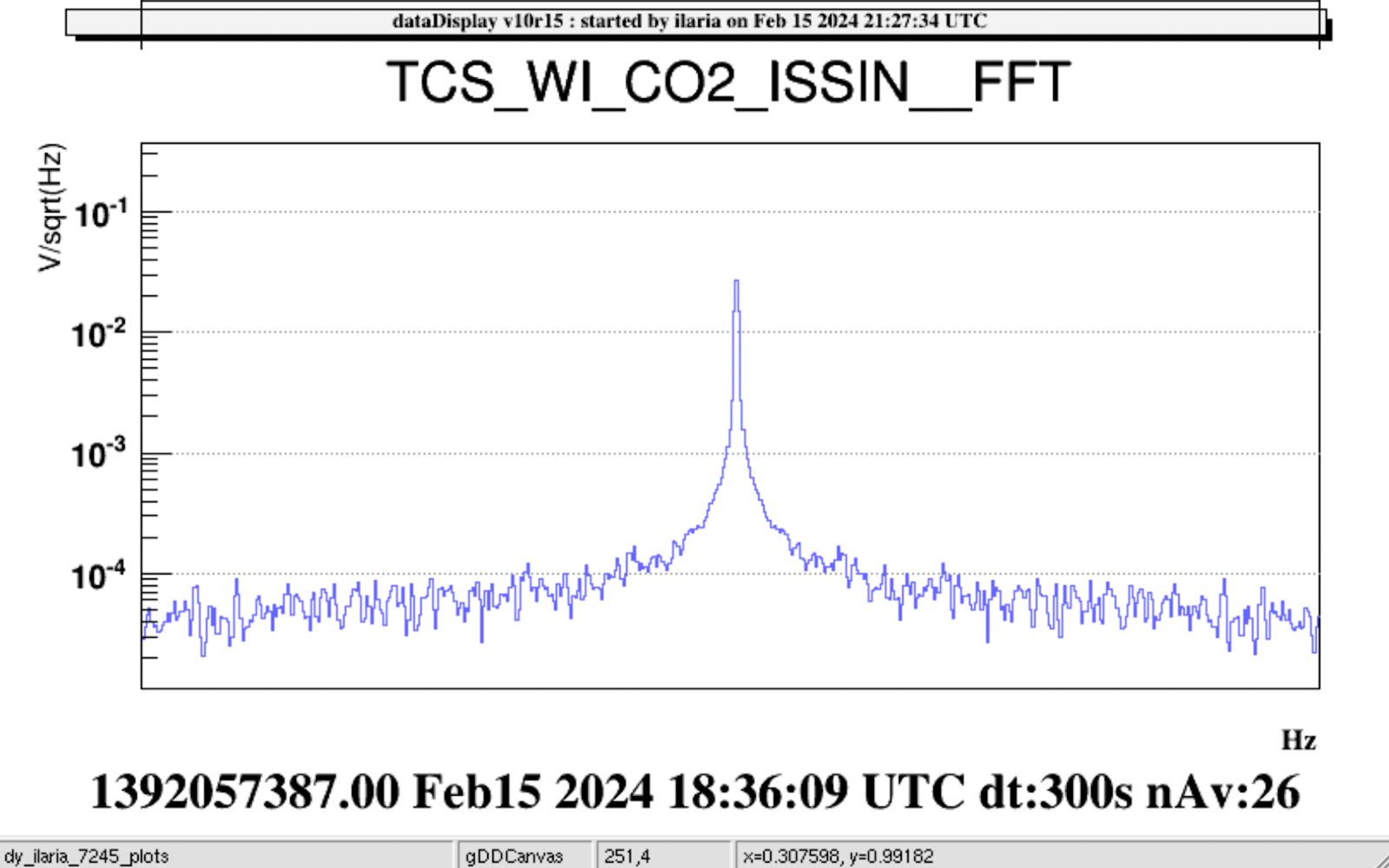
| 18.29.54 UTC GPS 1392057012 |
| 68 | 0.02 | 0.029 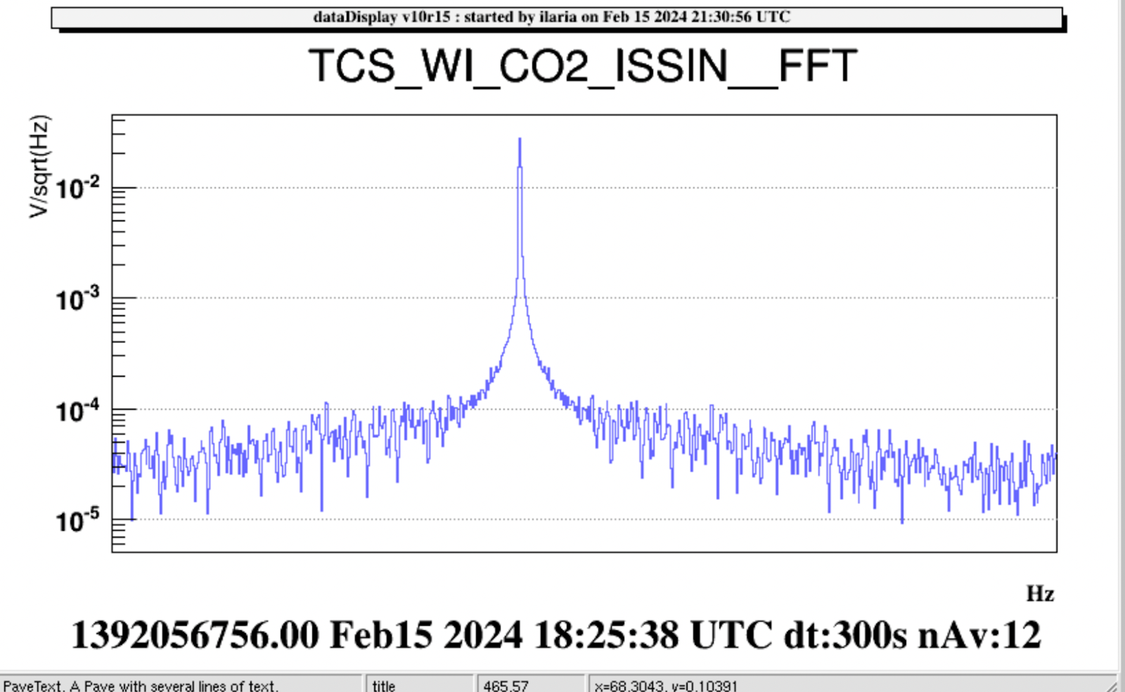
| 18.22.53 UTC 1392056591 |
| 85 | 0.02 | 0.027 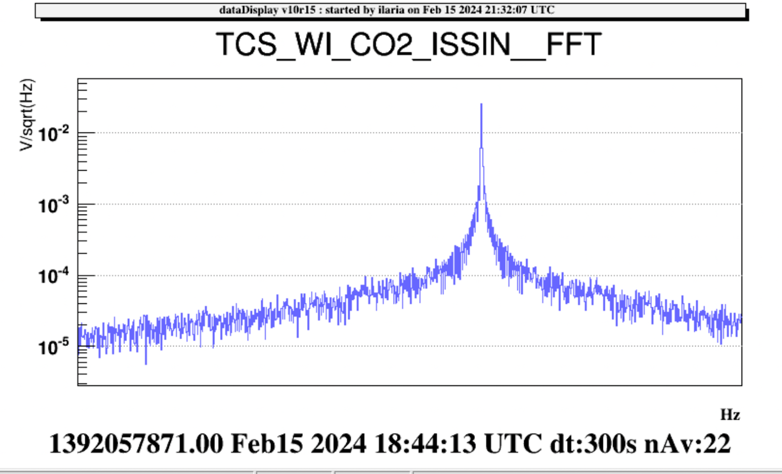
| 18.38.58 UTC 1392057556 |
NI
For the NI, the model predicts that with 4 V applied to the piezo, the expected values in hrec are 2.4*10^-21 1/sqrt(Hz)) at 29 Hz, 1*10^-21 1/sqrt(Hz) at 68 Hz and 8.7*10^-22 1/sqrt(Hz) at 85 Hz, to be compared with the measured ones reported in the table below. The measured values are lower by factor ~ 2 wrt the theoretical one.
| NI | Freq [Hz] | Amplitude [V] | TCS NI CO2 ISSIN [V/sqrt(Hz)] | Time | hrec [Measured] [1/sqrt[Hz]] | | | 29 | 4 | 0.225 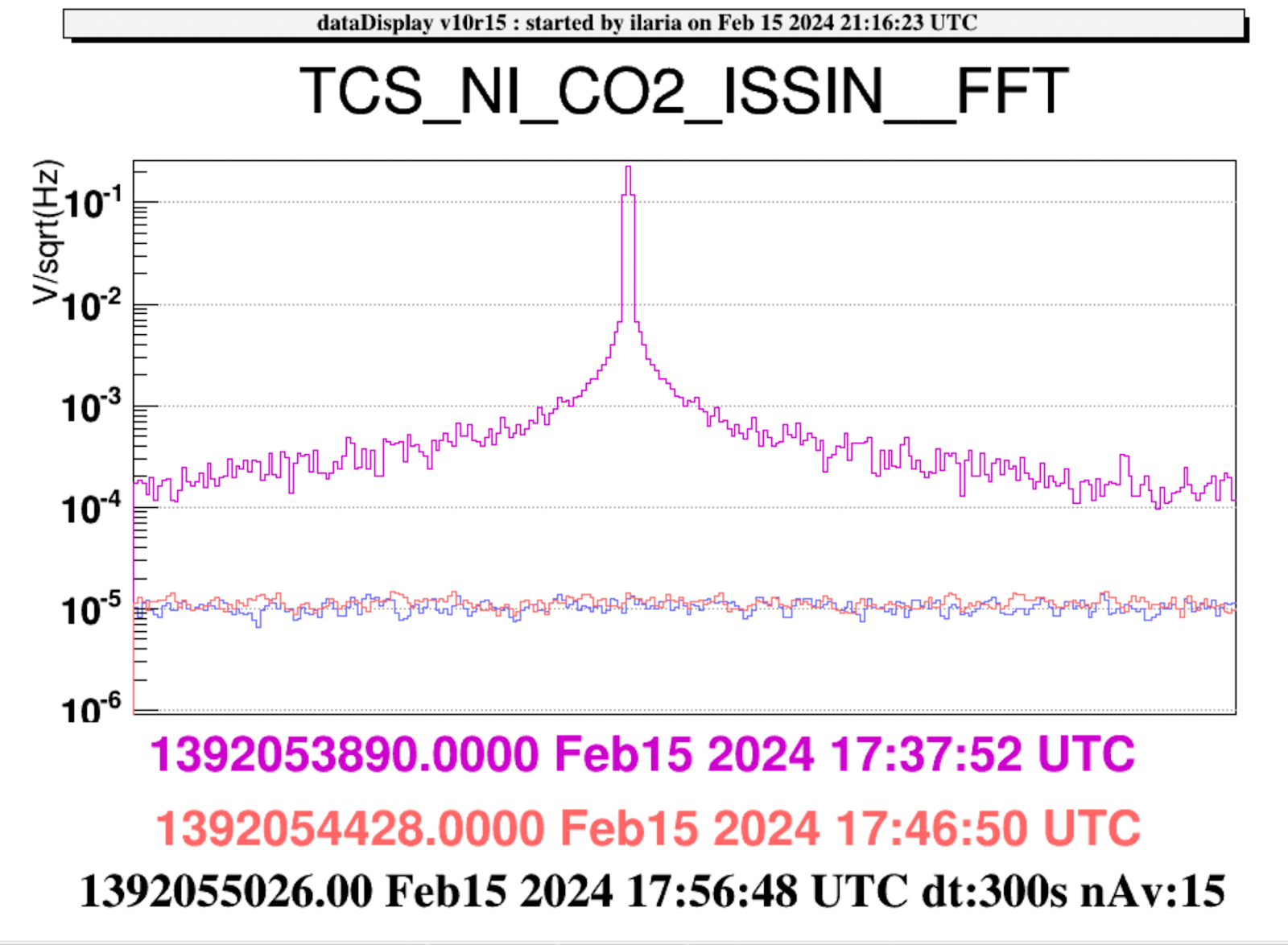
| 17.35.07 UTC (300 s) GPS 1392053725 | 1e-21 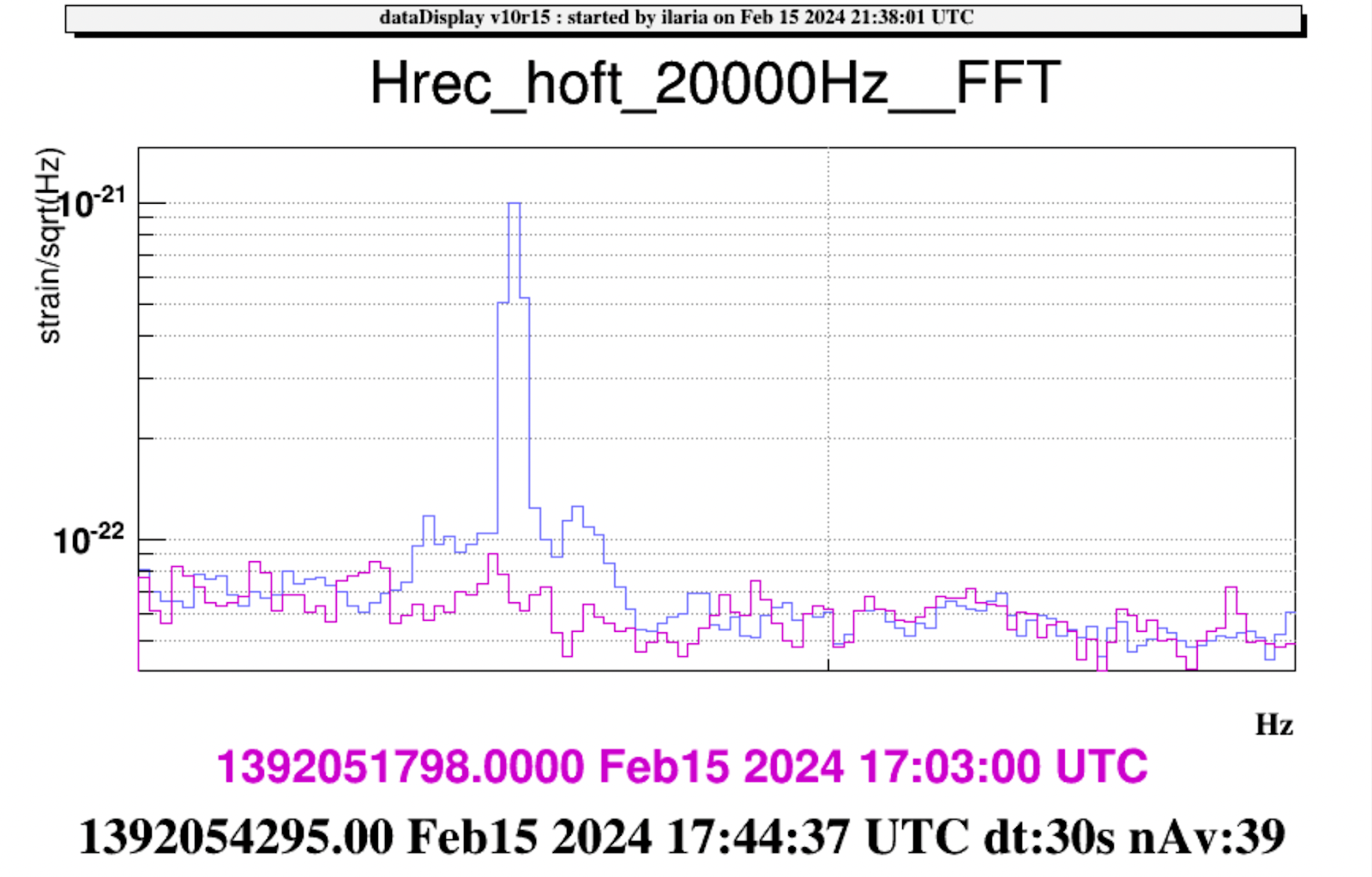 | | 68 | 4 | 0.187 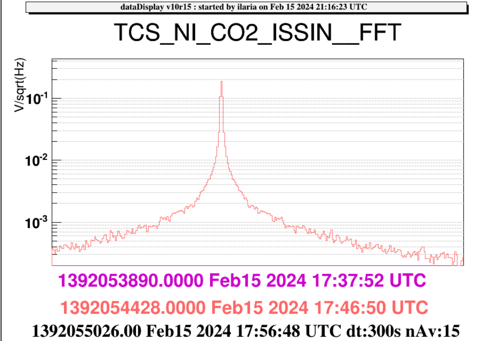
| 17.42.50 UTC (300 s) GPS 1392054188 | 4.5e-22 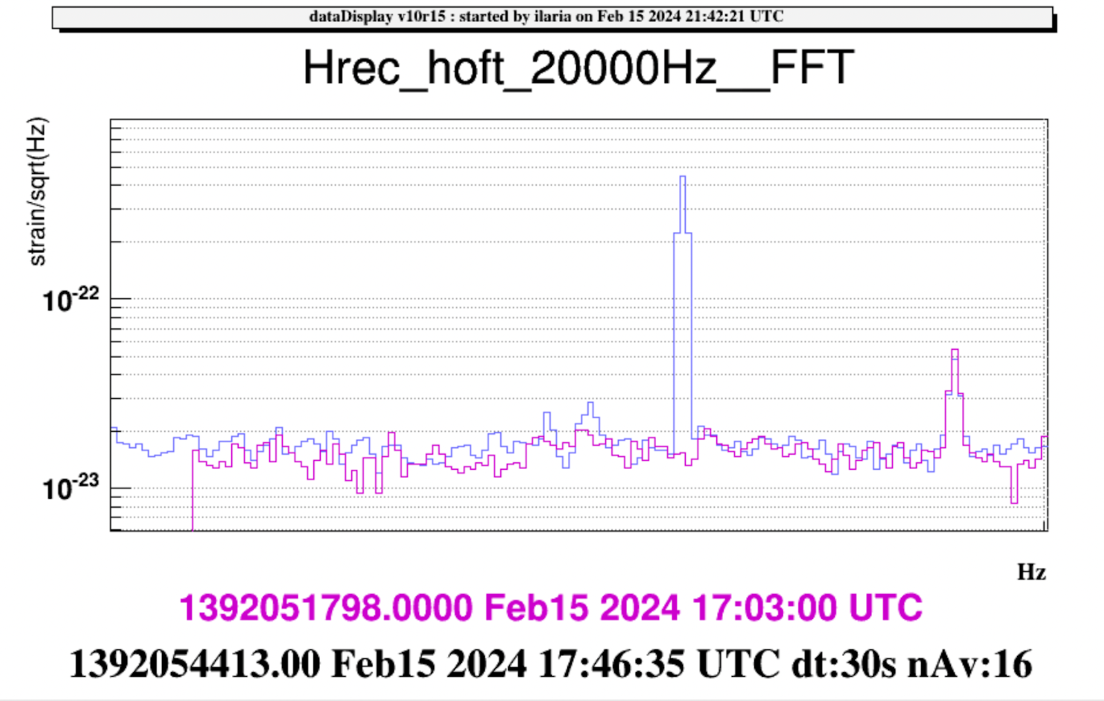
| | 85 | 4 | 0.198 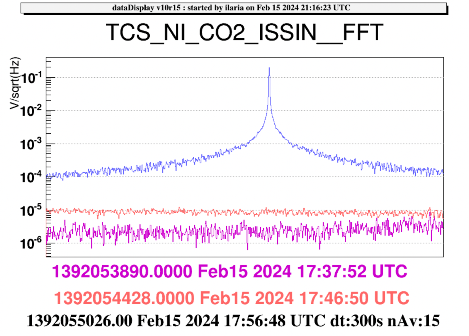
| 17.53.18 UTC (300 s) 1392054816 | 3.9e-22 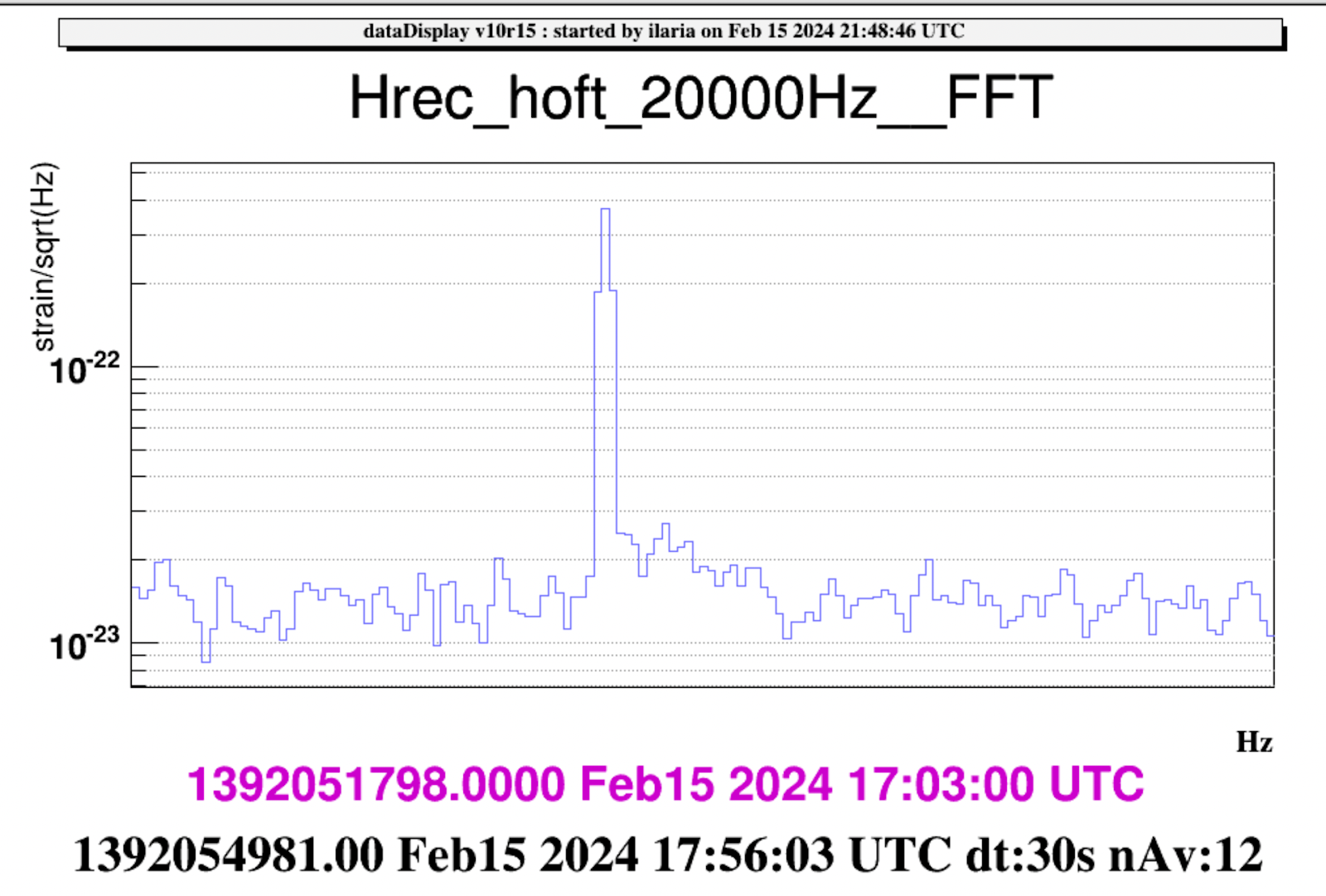
|
|
18.53 UTC: manual unlock
19.43 UTC: ITF in LN2
We repeated the noise injection on the NI at 85 Hz in LN2.
| NI/ LN2 | Freq [Hz] | Amplitude [V] | Time |
| | 85 | 4 | 19.58.59 UTC (300 s) GPS 1392062357 |
Unexpectedly in LN2 (with SR aligned), the line amplitude is lower wrt the configuration with SR mirror misaligned also in DARM (see fig.1) [ blue: SR aligned, purple SR misaligned].
=========================================================================================================
Once completed the noise injections, in agremeent with Fiodor, a common step has been applied on the ETM RH by increasing their power by 1.5 W.
To date:
NE: P_NE= 3.6W [ V=11.57 V]
WE : P_WE=4.55 W [ V=13.01 V]
At 20.07 UTC, the RH powers have been changed in:
NE: P_NE= 3.6W+1.5= 5.1 W [ V= 13.78 V]
WE : P_WE=4.55 W+1.5= 6.05 W [ V=15.00 V]


